After designing my own PCB with a previous schematic from the company, I understood the importance of thermal capacities of the design, especially during an overcurrent condition, in which the motor could pull over 3X the rated current.
I discussed thermal simulation strategies with the electrical team members, evaluated their previous workflow with Icepak, and found corrections that need to be made. Comparing with a thermal camera, I proposed a new model to evaluate thermal losses and completed preliminary verification using FlothermXT. This study was done on ST4, which is a servo motor encoder produced by Servotop.
Additionally, I redesigned the original thermal solution to a maximum of 58% temperature reduction at 3X overcurrent. More data will be discussed in the following content.
<ALL INFORMATION SHARED BELOW IS APPROVED BY THE COMPANY>
1. The Design
Jump to section 2 if you want to see some flow animation already!
1.1 Fan Choice
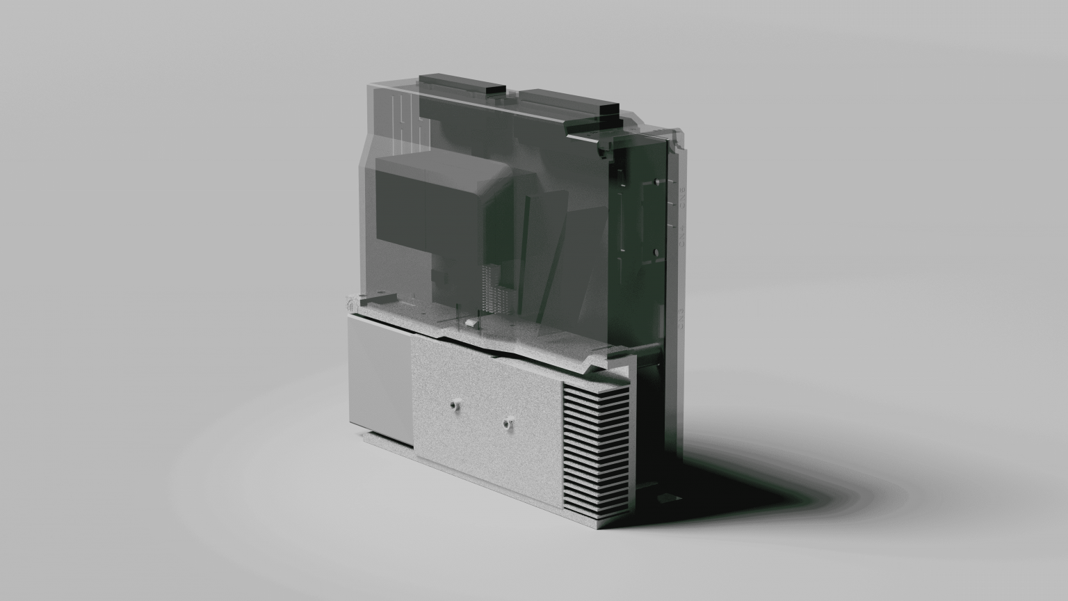
Considering we're working with the internals of a box-shaped device, to achieve maximum volumetric flow rate with a relatively small size of fan, I decided to go with the same-diameter centrifugal fan instead of an axial one used in the original design.
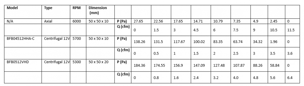
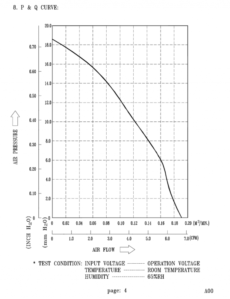
As we can observe from the two diagrams, the BFB0512VHD centrifugal fan allowed us to achieve a much higher static pressure, which is beneficial to promote airflow inside the internals of a boxed device.
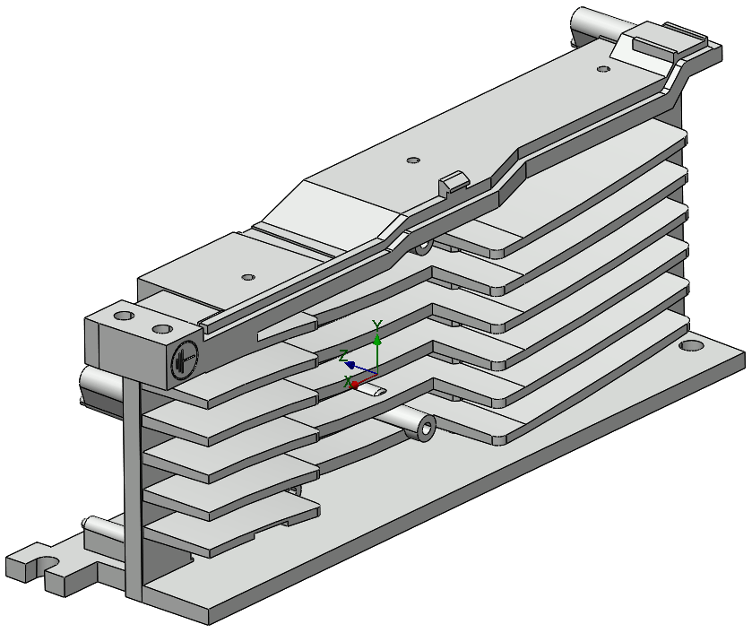
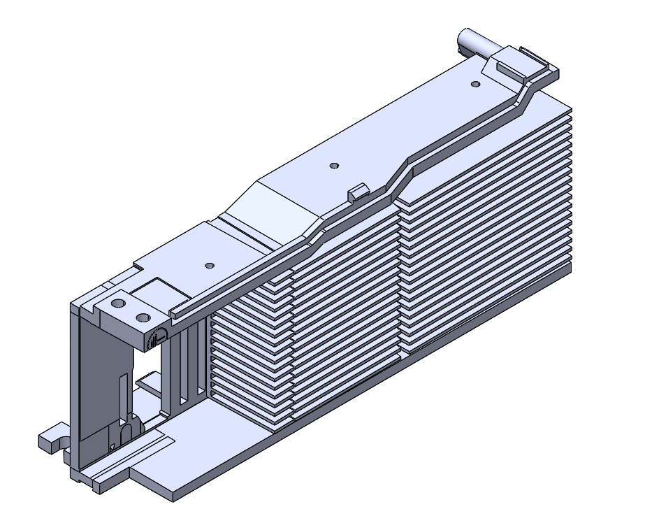
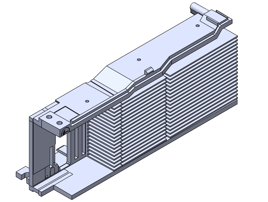
1.2 Radiator Geomatry
Fins
The original process of the radiator was die-cast aluminum alloy, which limits both fin thickness and fin gap to around 0.8 mm. Compared to the current thickness of the fins (1.92mm) and the gap between the two fins (5.67mm), there is still considerable room for improvement, yet doing so would raise the production cost in the process considerably.
Instead, I proposed to directly cast a flat surface. Given that the original process already involves a step of tapping threads on the same face, we could simply add several mounting holes to it and attach standardized aluminum fin parts with minimal cost. Doing this would bring the fin thickness to approximately 1mm, and the fin gap to 2mm.
This increases the convection area to around 2.5X the original.
Original Heat Sink
Re-designed Heat Sink
1.starting from the original design
2. Removes all fins and fan mounting
3. extruding ramp to avoid stagnation
4. cutting openings for fan intake
5.apply fins cut with angle
6. apply endcap (see below)
Endcap
During the simulation, I found out that the dip created in the center of the original design causes air to stagnate. Nearby streamlines are forced away from the radiator fins, leading to a significant loss in cooling performance.
By changing to a centrifugal fan that blows from the side and intakes from the inside of the device, we were able to create a ramp that helps to reduce such outwash in steps 3-4 of the images above.
This section introduces the use of an endcap to guide the flow of air through the fins in the new design.
top-down view. "/\" shape outwash not aligned with fins.
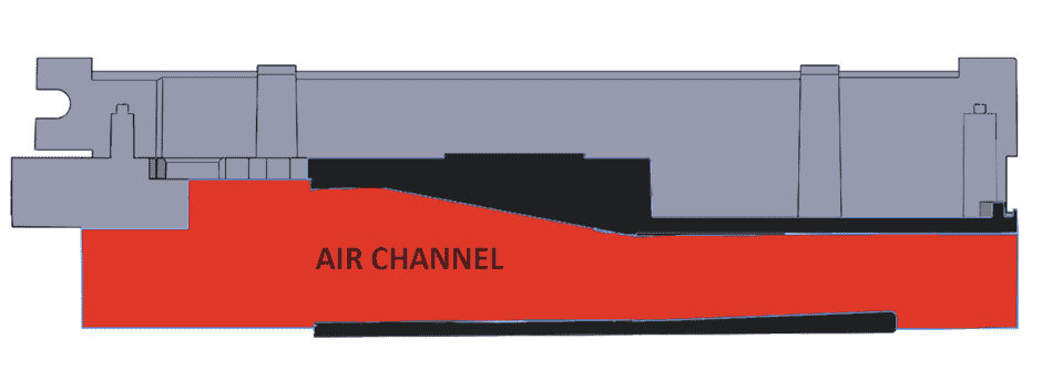
This is a cross-section cut of my new design. The black part shows where the material was clipped. The lower, long, and thin piece is the profile of the end cap. The red part shows how such an end cap and the original geometry form an air channel.
The airflow direction is as shown.
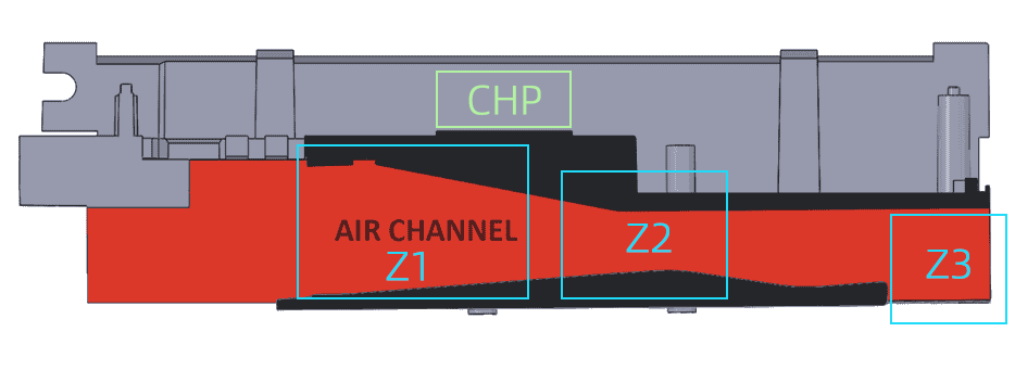
For illustration purposes, a more exaggerated version is created. We go through the channel characteristics by zones.
Z1: Air is forced through a smaller cross-section, so it accelerates. While doing so, it follows the direction of the fins and does not diverge.
Z2: the “throat”. Maximum airspeed causes increased turbulence, which increases the heat transfer coefficient, thus improving overall cooling performance. As the air accelerates from Z1 to Z2, its improved cooling capability takes away heat from CHP, the hottest chip in the device, which sits directly behind the black metal wall.
Z3: the end cap ends early (not aligned to the end of fins), so air is allowed to separate outwards, covering more fin area while doing so.
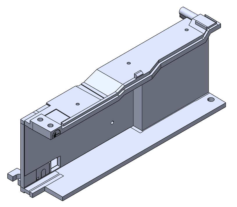
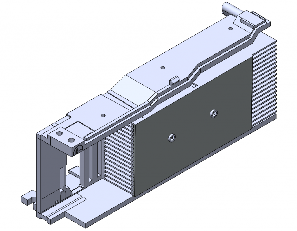
1.3 Chassy
The chassy also plays an important role as it defines the location of intake, and it's internal geometries is crutial as it molds the air path circulation within the device. This section introduces design changes and their justifications.
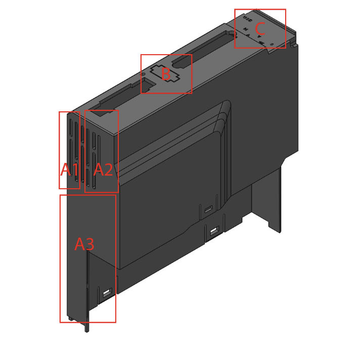
A1: Keep the opening, mainly for the air intake area at the back of the motherboard.
A2: Keep the opening, mainly for the air intake area at the front of the motherboard.
A3: Remove the opening, as there are no clear pathways due to large capacitors in the way.
B&C: This is the sealing done to simulate the position of the connectors blocking the opening of the chassy.
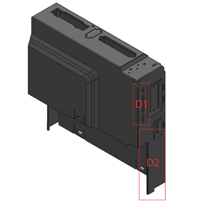
D1: Keep the opening. It serves as the second intake port for the front of the motherboard.
D2: Remove the opening. Because after the airflow test, it causes a backflow vortex and accumulation of hot air with the newly designed radiator.
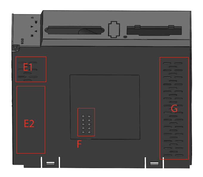
E1: Decorative hole, changed to actual through holes. Used for intake on the back of the motherboard.
E2: Remove the decorative hole.
F: Add through holes. As an additional intake port for the local heat dissipation fins for sampling resistors that gets very hot on the back of the motherboard.
G: Decorative hole, keep as is.
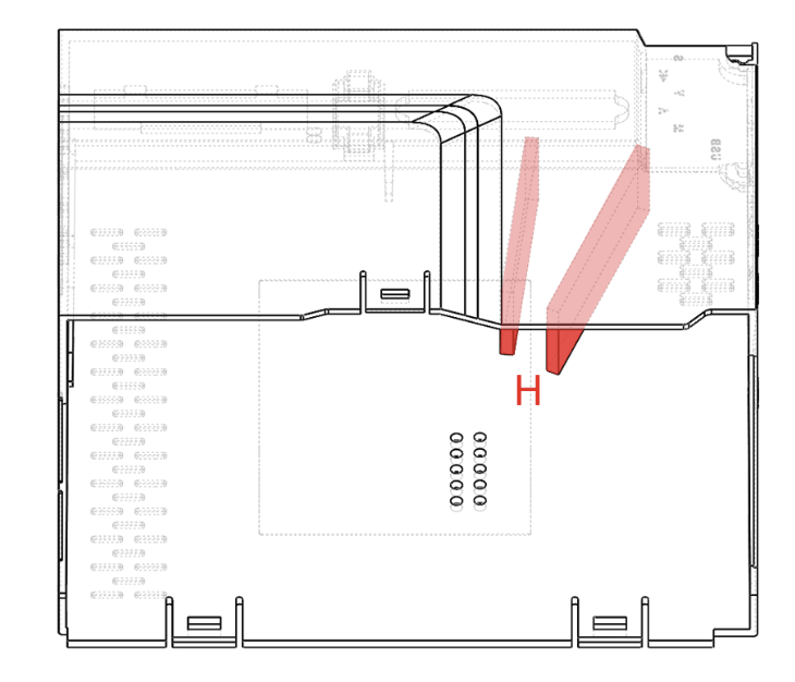
H: Two blockers added to control the direction and speed of the airflow. Effects will be evaluated below.
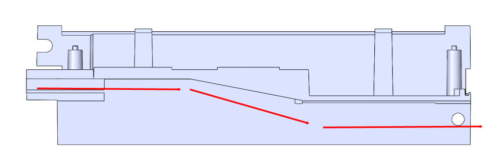
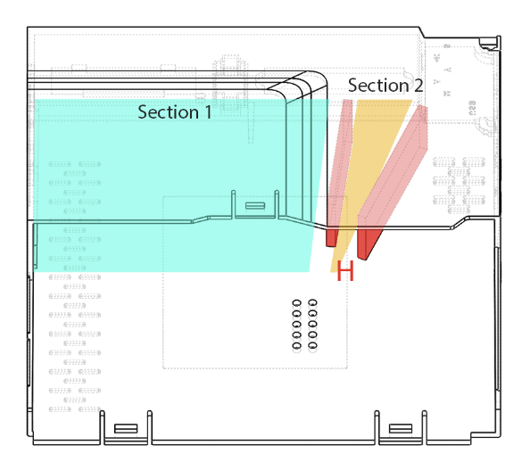
Section 1: The airflow passes around two capacitors. Airflow is encouraged by the pressure difference caused by the centrifugal fan.
Section 2: The airflow splits into this area, and accelerates through the funnel-shaped channel, extending downward to the right side of major heat generating components to provide higher speed airflow for heat dissipation.
2. The Flow
In this section, we explore the flow field resulting from these design considerations and compare them against the original design.
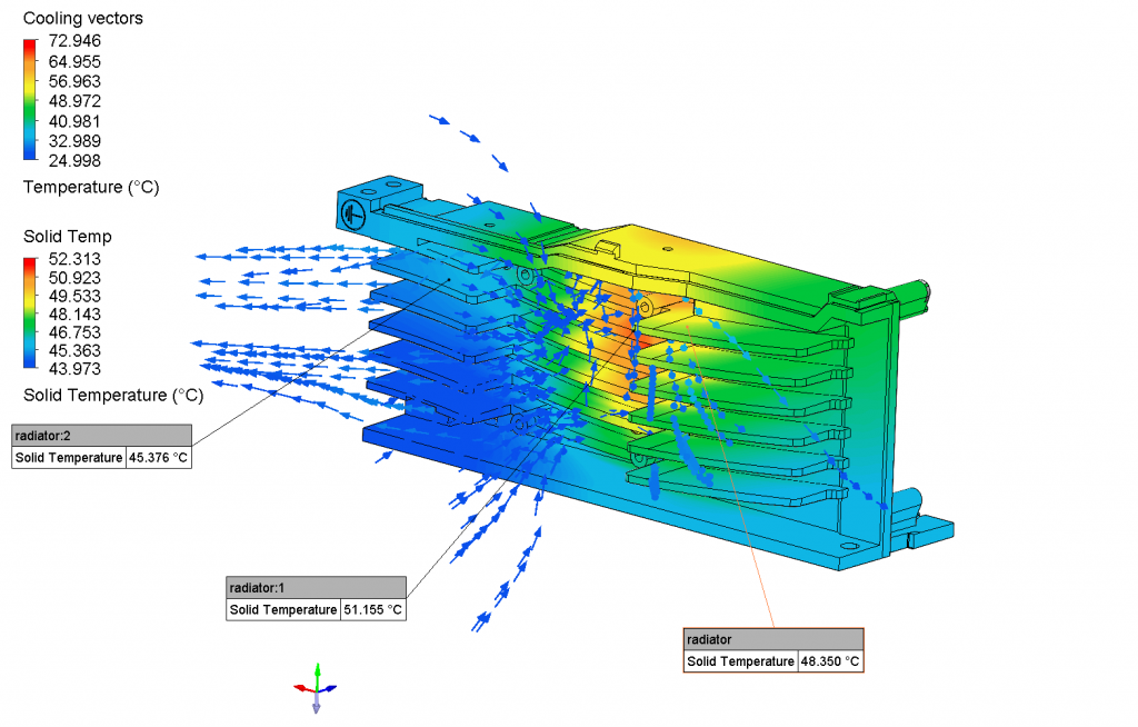
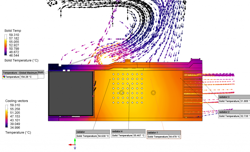
2.1 Radiator Airflow
We clearly observe that the airflow no longer diverges from the radiator in a “/\” shape, and there is no obvious stagnation. The channel created by the endcap and the inner wall of the radiator accelerated air through the fins, and the outwash downstream covered more fin area.
We also observe a small leak on the exterior of the fan. Attempts to extend the endcap to force it into the air channel have shown that it causes stagnation and decreases the airspeed in the channel. Since it does not create recirculation outside of the chassis, I decided to keep it as is.
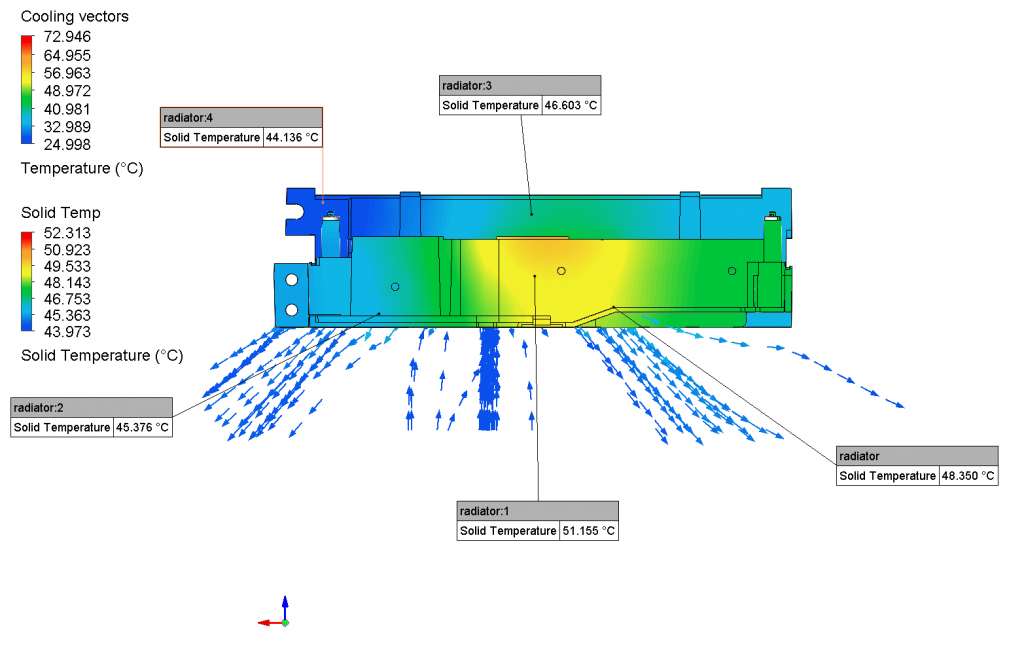
As anticipated, around the “throat”, the temperature of airflow is the highest as it absorbs a large amount of heat from the chip behind it, also as a result of increased heat transfer rate due to higher velocity.
The temperature distribution of the radiator is relatively even. The cold ~40 degrees part is a result of the high velocity air around the fan intake, so the radiator is cooled rapidly. Additionally, there isn’t significant heat generation in that region.
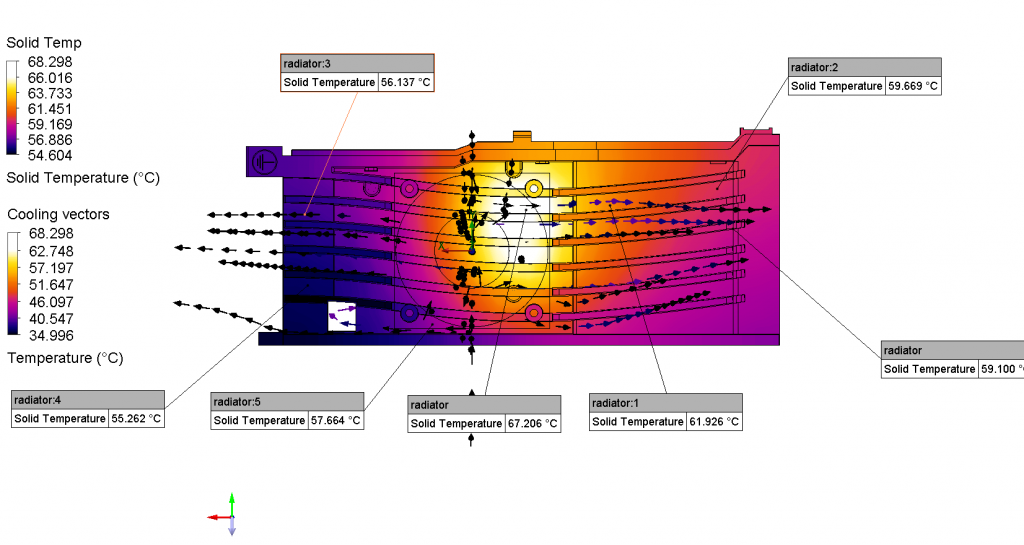
We can compare this temperature distribution with the original radiator.
New Design
Original Design
New Design
Original Design
Apparently, the new design:
Made the temperature distribution more even, which means better utilization of the material’s thermal mass.
Reduced the highest temperature by around 10 degrees, caused by denser fin and better flow characteristics.
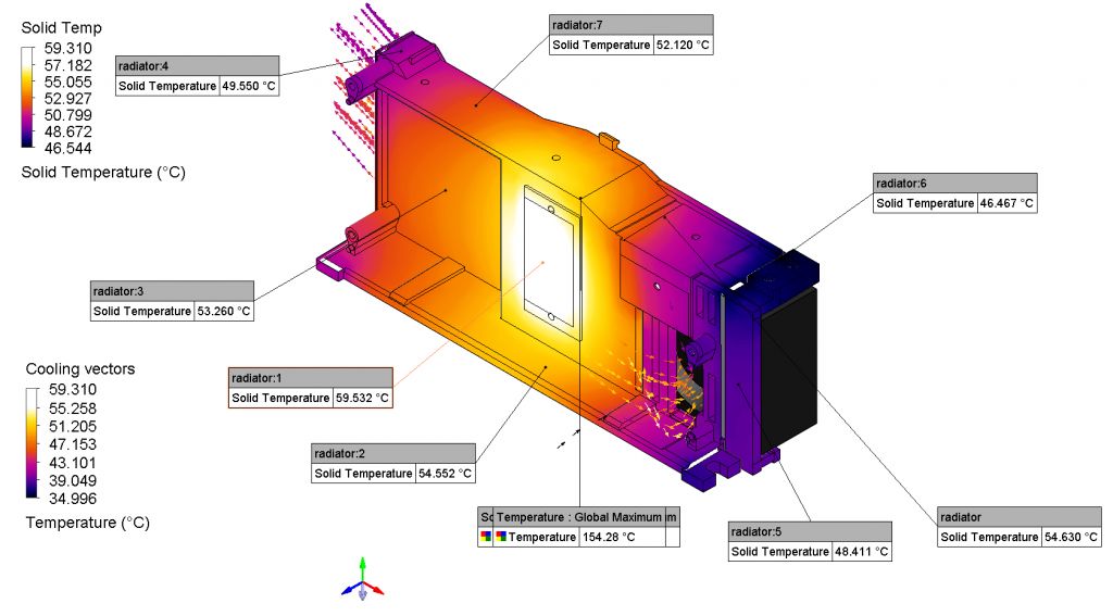
2.2 Chassy Airflow
On the left, we see the new design intakes from the top right corner and the back (see below). 2 air walls of the chassy were introduced in 1.3. They first guides the intake air around the two large capacitors to a local stick-on fin (two current-sensing resistors on the back of PCB generate a lot of heat) and takes away the heat. The second stream of air is guided to the right side of the major IC and flows through another local fin. The air then joins the first stream and exits through the radiator.
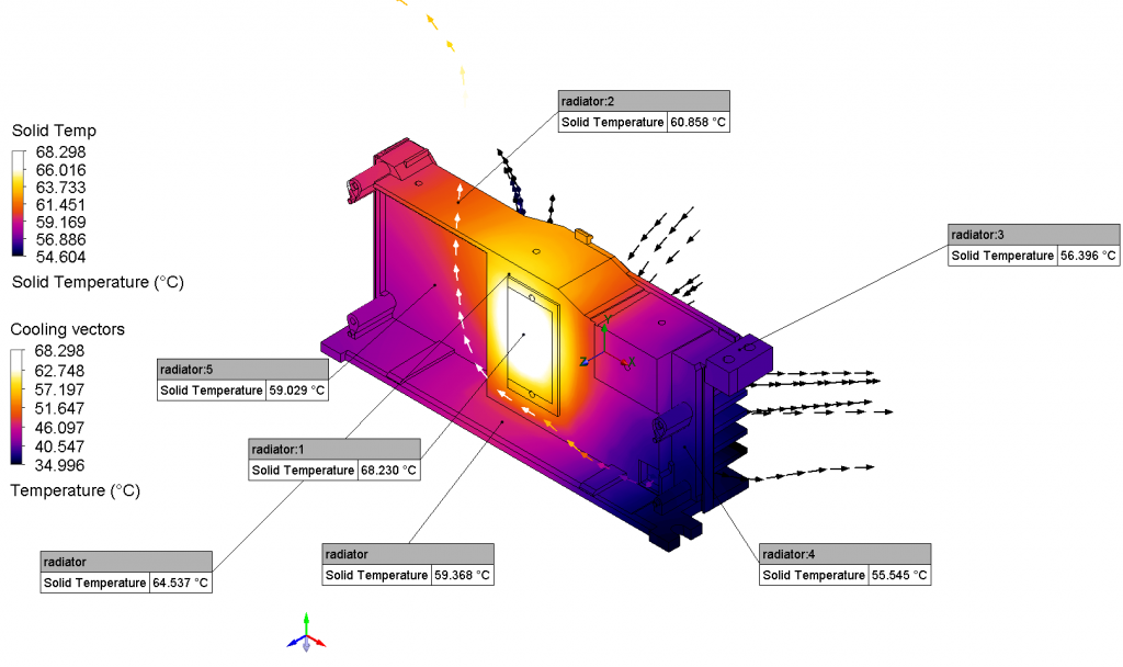
On the right, we see that air mostly recirculates in the device, and the airspeed is very low, especially around the two hot spots. Airflow created by the axial fan does not interact with the air inside the device, and there isn’t a clear logical airpath.
Temperature-wise, the new design clearly transfers heat to the incoming cold air more effectively, while the original design suffers from poor air velocity and recirculation. The maximum PCB temperature decreased by 95 degrees as a result of the new wind path, fan, and radiator. The temperature difference of the PCB is also lower, which lowers heat-induced stress.
On the back side, we see the new design takes in air from the top and left holes. Air accelerates towards the current sensing resistors while passing through 2 local fins, and eventually wraps around the PCB and into the fan.
The original design is much more chaotic; it doesn’t have sufficient pressure gradient to push air anywhere, and the openings of the chassis allow air intake and exit in any direction, so they can’t form any meaningful air path.
As a result, the heat transfer of the new design is much more efficient, and we clearly see a gradient of cool air being heated. The original design suffered from slow-moving air, and the passive convection around the resistor caused the local airflow to be heated extensively, and instead of carrying this heat out of the system, the slow air spreads the heat to other cooler areas of the PCB and deposits it into the board.
2.3 Air Path Interaction
Overall, we see a clear 2-layer structure of airflow with the new design. Air passes through the local fins on the bottom, converging towards the left end of the device, and then gets collected by the fan upwards, and lastly sent through the radiator towards the right.
The original design has fast-moving air on the top and, and it quickly diverges to the two sides due to radiator geometry. The air inside the device is mostly stationary.
Again, we clearly see the new design takes away heat in a more efficient manner.
3. The Data
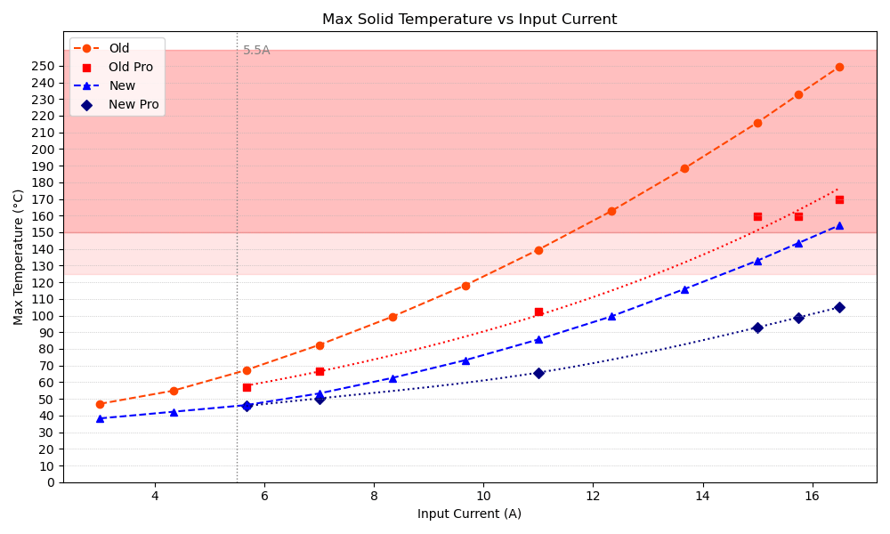
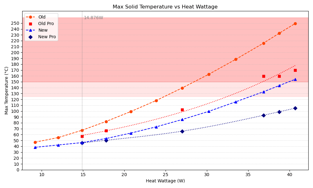
In this section, we conclude and visualize the performance of our redesigns. We start by defining several configurations of the device and their name used in the graphs.
Name in graph
configuration
Old
The original design without any modifications
Old Pro
The original design with 10 extra small local stick-on fin.
New
Modified radiator, fan, and chassy, with 5 local small sick-on fin.
New Pro
Modified radiator, fan, and chassy with 10 local small sick-on fin placed at same locations with Old Pro.
“Since the datapoint for “Old Pro” is limited due to time constrain, using spline or poly-fit could potentially cause the Runge effect. I used a least squares change of basis – exponential model to calculate the curve. “New Pro” uses a cubic natural spline due to similar reasons. The following graphs use same methods.
“New” and “New Pro” curves are lower in comparison to the original versions. With “New Pro”, the temperature at 16.5A is below 110 °C, which is theoretically where the device operates normally. This is the temperature of “Old” when it’s operating only at 9A. The maximum temperature at 16.5A decreased around 145 °C between “Old” and “New Pro”.
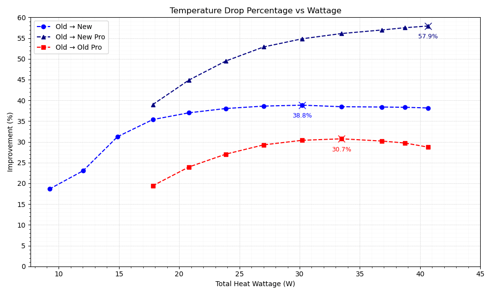
This graph shows the percentage temperature decrease between each pair of compared models at different heat wattages. Between “Old” and “New”, within 20W TDP, the temperature decrease is around 38.8%. Approaching 40W, the rate of temperature drop gradually decreases, reaching a maximum of 57.9% temperature drop. Comparing across the 3 curves, we can yet again see the massive influence small local radiating fins have.
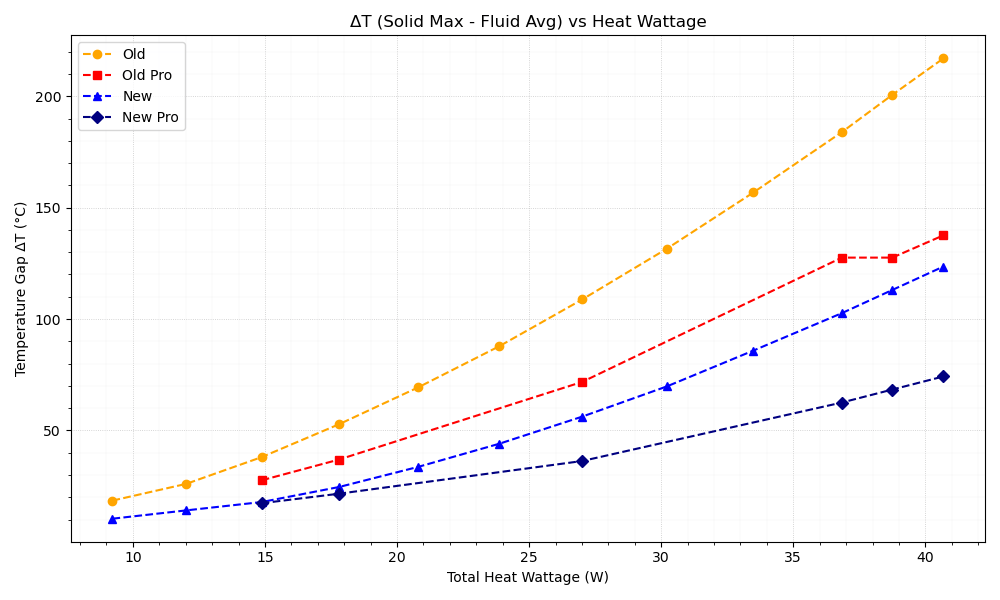
As the wattage increases, the temperature difference increases for all curves. The rate at which these curves go up represents the thermal exchange efficiency of the system – the smaller the slope, the stronger the exchange. We can see that although “New Pro” has the best exchange ability, all of “Old Pro”, “New”, and “New Pro” grow towards a similar pattern, whereas “Old” cuve climbs at a much faster rate. This confirms the models with small local radiating fins have better thermal exchange efficiency.